
Operating Gang Mode
This page was written for a previous version of Reality and has not been updated for the current Reality 5.4 SP1 release.

The following example contains three different Engines, as shown in the image above. All three Engines have the following setup in common:
Engines are launched with the same Unreal Project (*.uproject)
Engines are running in Configuration Mode
Engines have no RGraph

Create the node tree as shown on the image above by following connections:
EngineControlnode’sDisplayinput pin toMixer_0node’sProgramoutput pinMixer_0node’sChannel1input pin toCamera_0node’sOutputpinCamera_0node’sTrackinput pin toUserTrack_0node’sTrackpin
The node tree is ready.
Now:
Select the node tree except for the
EngineControlby clicking and holding your left mouse button and dragging over theUserTrack_0,Camera_0, andMixer_0nodesCopy the node tree you selected by pressing CTRL + C on your keyboard
Go to the Engine Toolbar, choose Engine02
Paste the node tree you copied earlier into Engine02’s Nodegraph by clicking CTRL + V on your keyboard
Connect the
Mixer_0node’sProgramoutput pin toDisplayinput of theEngineControlnode inside the Engine02Go to the Engine Toolbar, select Engine03
Paste the node tree you copied earlier into Engine03’s Nodegraph by clicking CTRL + V on your keyboard
Connect the
Mixer_0node’sProgramoutput pin toDisplayinput of theEngineControlnode inside the Engine03
Please remember that Gang Mode is a Nodegraph operation requiring identical Node types with the same name.
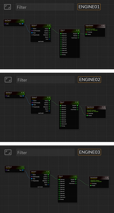
All three Engines have the same RGraph construction, as shown in the image above.
Now:

Activate the Gang Mode you learned in the earlier section

Select the
UserTrack_0node located inside the Engine01Go to
Inputproperties of theUserTrack_0Change the
User TransformXvalue from -500 to -400

Since all three Engines are included in the Gang Mode, the change you made in the User Transform X value is reflected in the Nodegraph of the Engine01 and the Engine03, as shown in the image above.
Last updated